MODERN PHYSICS

10 Nov 2016
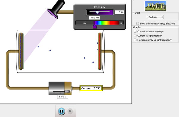
Photoelectric Effect is the phenomenon that when light shines on a metal surface, electrons are emitted from the surface.

Photoelectric Effect – A photon may knock an electron out of an atom and in the process itself disappear.

Electrons should be emitted when light shines on a metal is consistent with the electromagnetic wave theory of light – that is the electric field of an EM wave could exert a force on electrons in the metal and eject some of them

The process of measuring maximum kinetic energy can be done by using a variable voltage source and reversing the terminals so that the electrode C is negative and P is positive. The electrons emitted from P will be repelled by the negative electrode. But if this reverse voltage is small enough, the fastest electrons will still reach C and there will be a current in the circuit.

If the reverse voltage is increase, a point is reached where the current reaches zero, so no electrons have sufficient energy to reach C. This called stopping potential or stopping voltage

 Simulation 1: Click to runPhotoelectric Effect


Wave theory
Assume a monochromatic light. Two important properties of light are intensity and frequency. When two properties varied, the wave theory make prediction as below:
·         If the light intensity increase, numbers of electrons ejected and their maximum kinetic energy should be increased because – the higher the intensity, greater electric field amplitude and greater electric field should eject electrons with higher speed.
·         The frequency of the light should not affect the kinetic energy of the ejected electrons.

Photon theory
In monochromatic beam, all photons have the same energy, E=hf. Increasing the intensity of light mean increasing the number of photons.
  • ·         If the frequency remains the same, it does not affect the energy of each photon
  • ·         An electron is ejected from the metal by a collision with a single photon. Consequently, all the photon energy is transferred to the electron and the forces some minimum energy W0 (Work Function) is required to get an electron out through the surface.
  • ·         hf<W0 - The photon will not have enough energy to eject any electron
  • ·         hf>W0 – The electrons will be ejected and energy will be conserved.

Consideration of photon theory:
  • An increase in intensity of the light beams means more photons are incident, so more electrons will be ejected.
  • Since the energy of each photon is not changed, the maximum kinetic energy of electrons is not changed by increase in intensity
  • If the frequency is increased, the maximum kinetic energy of the electrons increases linearly.


Compton Effect
Compton Effect – a photon can be scattered from an electron and in the process, lose some energy. But the photon is not slowdown; it still travels with speed, c but its frequency will be lower.

Compton scattered short wavelength light, which is X-rays, from various materials. He found that the scattered light had a slightly longer wavelength than the incident light, therefore, there is a slight lower frequency indication loss of energy.

Since the photon is relativistic particle that travel with the speed of light, v= c, the momentum of photon is


Figure 1: Compton Scattering

Atomic Structure
 In 1911, Ernest Rutherford (1871-1937) theorized that the atom must consist of a tiny but massive positively charged nucleus, surrounded by electrons some distance away. The electrons would be moving in orbits about the nucleus.


Figure 1: Atomic Structure


Line Spectrum of Hydrogen Atom


Figure 2: Hydrogen Atom

Hydrogen is simplest atom that has only one electron orbiting its nucleus. It atomic number is 1.

In 1885, J. J. Balmer showed that the four visible lines in the hydrogen spectrum (with wavelength 656 nm, 486 nm, 434 nm and 410 nm) fit the following formula


Later was found that this Balmer series of lines extended to UV region, ending at = 365 nm


Figure 3: Electron transitions for the Hydrogen atom


Wave-Particle Duality


Some indicate that light behaves like waves and the other indicates light behaves like stream of particles. These behaviours of light come in to conclusion as wave-particle duality.

In 1923, Louis de Broglie suggests that the wavelength of a particle would be related to its momentum as in the same way with photon. 


p = linear momentum
= wavelength

Sometimes it is called the de Broglie wavelength of a particle


Video 2: Waves-Particle Duality


Diffraction of X-Ray


X-ray is produced when electrons accelerated by a high voltage strike the metal target inside the X-ray tube. W. C. Roentgen in 1895 discovers the X-ray using voltages of 30kV – 150 kV. H-rays scattered from a crystal did indeed show the peaks and valleys of a diffraction pattern. It was shown that X-rays have a wave nature and the atoms are arranged in a regular way in crystals (serve as diffraction) Today, X-rays are recognized as electromagnetic radiation.   

The diffraction of X-rays with wavelength,  that a reflection from a crystal as described by Bragg equation. Strong reflections are observed at grazing angles  given by,


= distance between reflecting planes in the crystal
 = angle between the face of the crystal

m = reflected beam in order of reflection = 1, 2, 3, ...


Video 3: X-Rays Diffraction


Read more ...

MAGNETISM

5 Nov 2016
MAGNETISM

A Magnetic Field (B) exists in an otherwise empty region of space if a charge moving through that region can experience a force due to its motion.


Figure 1Magnet bar with iron sprinkled 
around it forming line up with magnetic field
 Figure 2A magnetic field lines
representing this magnetic field


In Figure 2, the magnetic field lines represent both the magnitude and direction of the magnetic field vector. The magnetic field vector at any point is tangent to the field line and the magnitude of the field is proportional to the number of lines per unit area perpendicular to the lines.
The bar magnet is one instant of a magnetic dipole. Magnetic dipole consists of two opposite magnetic poles:
  • The end of the bar magnet where the field line emerge is called the north pole
  • The lines goes back in called south pole

Magnetic field lines are all closed loops. If there are no magnetic monopole, there is no place for the field lines to begin or end.


MAGNETIC FORCE ON A POINT CHARGE

Electric field is defined as the electric force per unit charge.

q = a point charge

The electric force is either in the same direction as E or in the opposite direction depends on the sign of the point charge

The magnetic force depends on the point charge’s velocity as well as on the magnetic field. If the charge is at rest, there is no magnetic force. The magnitude and the direction of the magnetic force depend on the direction and speed of the charge’s motion. The magnetic force increases in magnitude with increasing velocity. The direction of the magnetic force on a charged particle is perpendicular to the velocity of the particle.

Factors a charge moving in a magnetic field:
  • The magnitude of the charge, q
  • The strength of the magnetic, H
  •  The magnitude of the velocity of the charge, v or the component of the velocity                perpendicular to the field
  • Sin ,  is the angle between the field lines and the velocity, v

Magnitude of the magnetic force on a moving point charge:


The SI unit of magnetic field is N/A m or tesla, T.


The direction and the magnitude of the magnetic field force depend on the vector v and B. The magnetic force can be written in term of the cross product (vector product). 

Let  and 


The vector products have perpendicular directions to the vectors. It can be determined using the right-hand-rule.


Video 1: Magnetic Force and The Right-Hand-Rule


MAGNETIC FORCE ON A CURRENT CONDUCTOR

A conductor carrying electric current has many moving charges in it. For a current carrying conductor in magnetic field, the magnetic forces  on moving charges add up to produce a net magnetic force on the wire.

A straight wire segment of length, L in a uniform magnetic field B carries a current I
The mobile carriers have charge, q
The magnetic force on any one charge is
 v is the instantaneous velocity of the charge
Multiply the average magnetic force on each charge by the number of charges 
 If N is the total number of carriers in the wire, the total magnetic force on the wire is
Magnetic force in terms of current, 

            n is the number of carriers per unit volume
            If the length, L and the cross-sectional area is A, then


Number per unit volume x volume =  nLA

             In substitution, the magnetic force on the wire is

       The magnetic force on a straight segment current carrying conductor 


        The current I times the cross product L x B gives the magnitude and direction of the               force


Figure 3: A current-carrying conductor in a magnetic field experiences a magnetic force


       (a)    A wire suspended vertically between the poles
       (b)   The blue x represents the magnetic field. When there is no current, the wire remain                 vertical
       (c)    If the current going upwards, the wire deflects to the left
       (d)   If the current going downwards, the wire deflects to the right 


       MAGNETIC FIELD DUE TO AN ELECTRIC CURRENT

       Magnetic field due to a Long Straight Wire

      Using the right-hand-rule to find the direction of the magnetic field due to a long straight wire:
  •       Point the thumb of the right hand in the direction of the current in the wire
  •       Curl the fingers inward toward the palm
  •          The direction that the fingers curl is the direction of the magnetic field lines around the wire 


Figure 4: Right-hand-grip-rule

      The magnitude of the magnetic field at a distance r from the wire can be found using        Ampere’s Law:
       
              I   = current in the wire

           =  universal constant known as the permeability of free space, 


Video 2Magnetic Field Pattern due to Electric Current in a Straight Wire


      Magnetic field due to a circular current loop

      Using right-hand-rule to find the direction of the magnetic field due to a circular loop of current:
  • ·         Curl the fingers of right hand inward toward the palm, following the current around      the loop
  • ·         The thumb points in the direction of the magnetic field in the interior of the loop

Figure 5: Magnetic fields due to a circular current loop


       The magnitude of the magnetic field at the center of circular loop is

      N = the number of turns
       I = the current
       r = radius
                     
      Torque on a coil in a uniform field,  on a coil of N loops, each carrying a current I in a               external magnetic field, B is


      A = area of the coil
   = the angle between the field lines and a perpendicular to the plane of the coil


Video 3: Magnetic Field 


      Magnetic field due to a solenoid

Figure6: Magnetic field lines due to a solenoid. The blue lines represent the wire crossing the coil with current 

       The magnetic field strength inside a solenoid is given by


       n = N/L, the number of turns per unit length


Video 4: Magnetic Field in Solenoid


Read more ...